Introduction
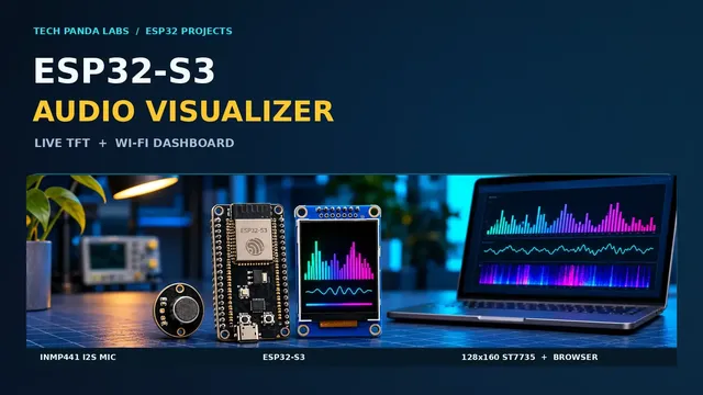
Build a real-time ESP32-S3 audio visualizer that listens through an INMP441 digital microphone, renders sound-reactive graphics on a 1.77-inch ST7735 TFT display and hosts a browser dashboard over Wi-Fi. The project, called Spectra Studio in its firmware, brings spectrum bars, waveform graphics, a waterfall view, audio-level indicators and estimated beat detection together on one microcontroller.
This guide follows the hardware connections, PlatformIO workflow and result shown in the project video. The published source code is the reference implementation. Although the video uses the general phrase FFT spectrum analyzer, the published firmware computes 32 frequency-band estimates with the Goertzel algorithm, rather than running a conventional full FFT. Both are frequency-analysis approaches, but they are not identical.
What you will build
The assembled project has two simultaneous outputs:
- Local TFT: colorful sound-reactive spectrum bars, waveforms, level indicators and animated effects on a 128 × 160 ST7735 screen.
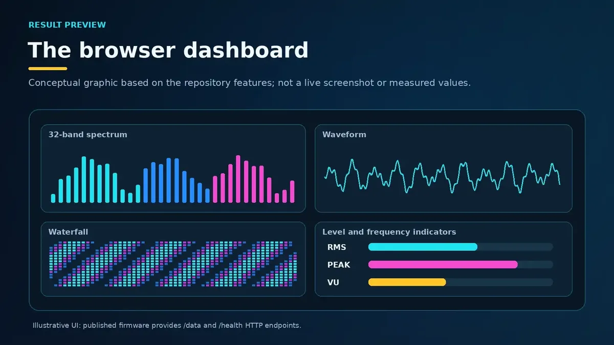
- Wi-Fi dashboard: an interface in a browser with frequency bands, waveform and waterfall visualizations, RMS/peak/VU indicators, estimated dominant frequency, beat and low/mid/high band information.
The ESP32-S3 acquires the microphone samples and performs the analysis locally. It serves the dashboard and the latest measurements to devices on its network; the browser renders the larger graphics. No PC is required to perform the audio analysis once the firmware is running.
What you will need
Components
| Qty | Component | Notes |
|---|---|---|
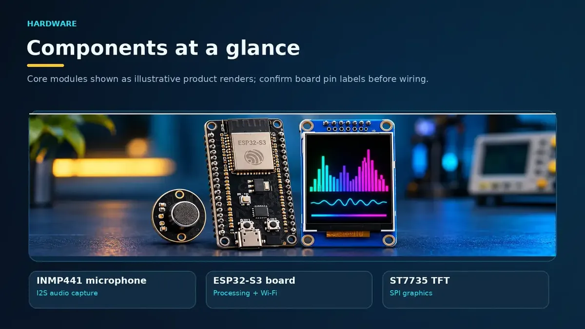
| 1 | ESP32-S3 DevKitC-1 compatible board | Main controller; choose a board exposing the listed GPIOs. |
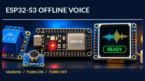
| 1 | INMP441 I2S microphone breakout | 3.3 V digital microphone; left-channel select is grounded. |
| 1 | 1.77-inch ST7735 SPI TFT display | 128 × 160 version shown in the published configuration; check your module's pin labeling. |
| 1 set | Jumper wires | Connect the breakout modules to the ESP32-S3. |
| 1 | USB data cable | Powers the controller and uploads firmware. |
Software
- Visual Studio Code with the PlatformIO extension.
- Arduino framework for the ESP32-S3 DevKitC-1 PlatformIO target.
- TFT_eSPI, configured for ST7735. The reference project specifies bodmer/TFT_eSPI@^2.5.43.
- The Tech Panda audiovisualizer repository, including the firmware and original AI coding prompt.
- A 2.4 GHz Wi-Fi network and a browser on the same network for the dashboard.
Prerequisites
You should be able to identify 3.3 V, ground and GPIO labels on your particular ESP32-S3 board; install the PlatformIO toolchain; and upload a basic firmware build over USB. Different ST7735 breakout boards can use different pin names, backlight circuits and color-tab configurations.
How it works
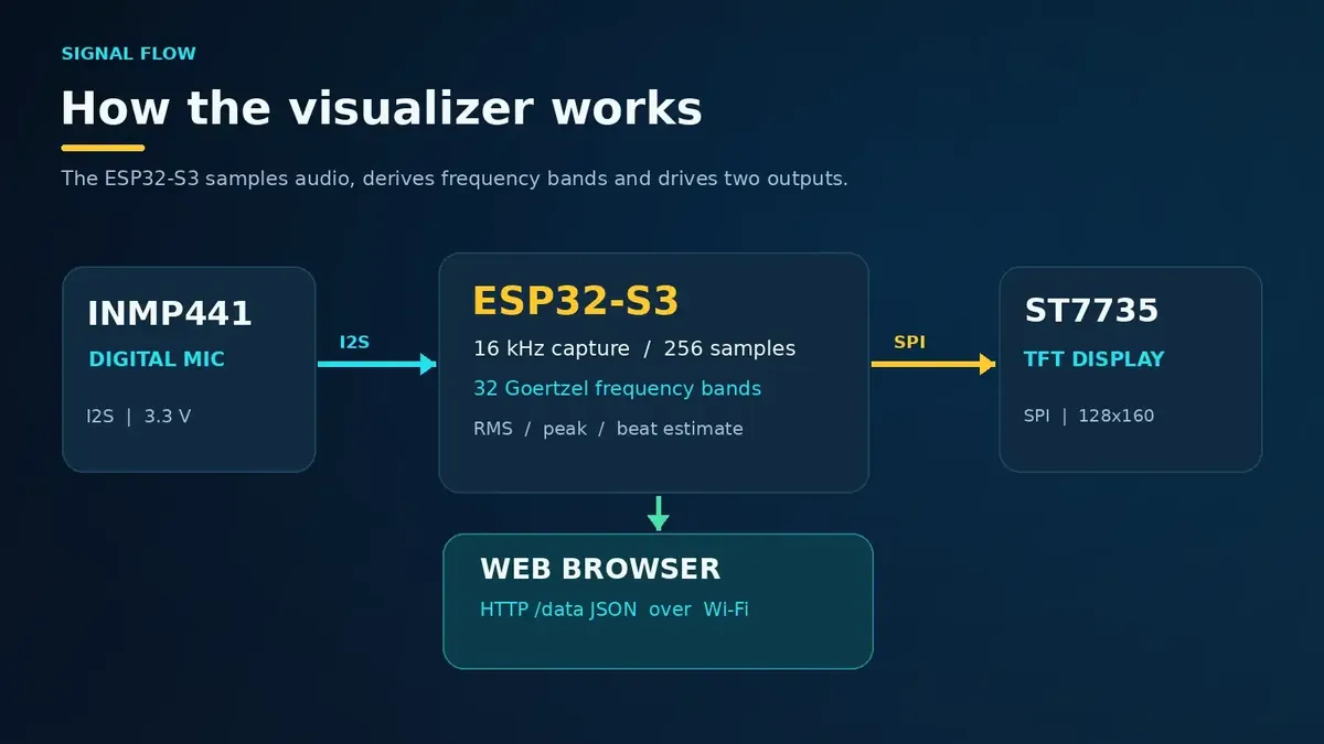
The INMP441 sends digital audio through I2S. This is not I2C: I2S uses separate word-select (WS/LRCLK), bit-clock (SCK/BCLK) and serial data (SD) lines. The ESP32-S3 samples the microphone at 16 kHz and processes 256-sample blocks in the published firmware.
For each audio block, the firmware applies a window, evaluates 32 selected frequency bands using Goertzel calculations, and derives quantities used for the VU meter, RMS, peak estimates, beat response and approximate peak frequency. The reported peak is derived from the strongest analyzed band; it is not a laboratory-grade frequency measurement.
At the same time, the controller updates the TFT over SPI and serves the browser UI over Wi-Fi. The code uses Arduino WebServer with an HTTP JSON endpoint at /data plus /health; it does not implement a WebSocket stream. The browser requests fresh data repeatedly and animates its own spectrum, waveform and waterfall displays.
Understanding the pins
- SPI: MOSI carries screen commands and pixels; SCLK clocks the transfer; CS, DC and RST select, differentiate and reset the display.
- I2S: WS selects the audio channel, SCK clocks the samples and SD carries the microphone's data toward the ESP32.
- L/R: tied to ground in this build to select the microphone's left channel.
- MISO: the repository defines TFT_MISO=37, but the demonstrated write-oriented TFT wiring does not specify a connected MISO line. Do not invent a MISO connection on a display that has no data-output pin.
Wiring and connections
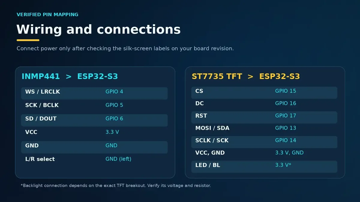
Use the exact ESP32 GPIO assignments from the video and the reference project. The Pin column names the pin on the peripheral module; Signal names the connection on the ESP32-S3.
ST7735 TFT display
| Pin | Signal | Notes |
|---|---|---|
| CS | ESP32-S3 GPIO15 | TFT chip select. |
| DC | ESP32-S3 GPIO16 | Data/command select. |
| RST | ESP32-S3 GPIO17 | Display reset. |
| MOSI / SDA | ESP32-S3 GPIO13 | SPI data toward the TFT; this is not I2C SDA. |
| SCLK / SCK | ESP32-S3 GPIO14 | SPI clock. |
| VCC | 3.3 V | Check the module's supply rating before powering it. |
| GND | GND | Common ground. |
| LED / BL | 3.3 V, if suitable for the module | Video demonstrates this connection; verify whether your board includes backlight current limiting. |
INMP441 I2S microphone
| Pin | Signal | Notes |
|---|---|---|
| VCC / VDD | 3.3 V | Never connect the microphone supply directly to 5 V. |
| GND | GND | Common ground. |
| WS / LRCLK | ESP32-S3 GPIO4 | I2S word-select. |
| SCK / BCLK | ESP32-S3 GPIO5 | I2S bit clock. |
| SD / DOUT | ESP32-S3 GPIO6 | I2S audio data from microphone. |
| L/R | GND | Select the left audio channel. |
Disconnect USB power while wiring. Confirm that every module shares ground, and verify that all display signals and the microphone are operating at 3.3 V logic levels.
Assembly and setup
Step 1
Place the ESP32-S3, TFT screen and INMP441 where all pin labels are visible. Disconnect USB power.
Step 2
Wire the TFT's CS, DC, ST, MOSI and SCLK to GPIO15, GPIO16, GPIO17, GPIO13 and GPIO14 respectively. Connect display power and ground according to the module specification.
Step 3
Wire the microphone's WS, SCK and SD to GPIO4, GPIO5 and GPIO6. Connect VCC
to 3.3 V, GND to ground and L/R to ground.
Step 4
Inspect the connections for reversed power pins, loose jumper wires and accidental shorts. Only then reconnect the ESP32-S3 to USB.
Step 5
Obtain the public project code, open its root folder in VS Code, and let PlatformIO install the dependencies.
Step 6
Set your own Wi-Fi credentials in a local, untracked
src/secrets.h
file before compiling (see below).
AI coding prompt
The video demonstrates a VS Code/PlatformIO agentic coding workflow that generates the firmware, screen renderer and browser dashboard. To recreate that workflow, open the original AI agent prompt and give it to your coding assistant in an empty ESP32-S3 PlatformIO project.
That prompt specifies the hardware, ST7735 build flags, the I2S pin mapping, 16 kHz audio processing, a 32-band spectrum, a local web dashboard and HTTP JSON outputs. The generated output must still be reviewed, compiled, and tested against your actual board and display before use.
If you prefer the source demonstrated in the video, clone the published repository instead of generating a new implementation.
Project configuration
The public repository uses the PlatformIO environment esp32-s3-devkitc-1, Arduino, and TFT_eSPI. These are the relevant display definitions from its platformio.ini:
[env:esp32-s3-devkitc-1] platform = espressif32 board = esp32-s3-devkitc-1 framework = arduino monitor_speed = 115200 lib_deps = bodmer/TFT_eSPI@^2.5.43 build_flags = -D USER_SETUP_LOADED=1 -D USE_FSPI_PORT=1 -D ST7735_DRIVER=1 -D TFT_WIDTH=128 -D TFT_HEIGHT=160 -D ST7735_REDTAB=1 -D TFT_CS=15 -D TFT_DC=16 -D TFT_RST=17 -D TFT_MOSI=13 -D TFT_SCLK=14 -D TFT_MISO=37 -D SPI_FREQUENCY=4000000[env:esp32-s3-devkitc-1] platform = espressif32 board = esp32-s3-devkitc-1 framework = arduino monitor_speed = 115200 lib_deps = bodmer/TFT_eSPI@^2.5.43 build_flags = -D USER_SETUP_LOADED=1 -D USE_FSPI_PORT=1 -D ST7735_DRIVER=1 -D TFT_WIDTH=128 -D TFT_HEIGHT=160 -D ST7735_REDTAB=1 -D TFT_CS=15 -D TFT_DC=16 -D TFT_RST=17 -D TFT_MOSI=13 -D TFT_SCLK=14 -D TFT_MISO=37 -D SPI_FREQUENCY=4000000
The displayed block is an extract, not the entire configuration. Use the repository's
platformio.ini as the source of truth. Your own ST7735 variant may need different settings.
Add Wi-Fi credentials locally
The published main.cpp includes "secrets.h" . Create src/secrets.h beside src/main.cpp
and define the identifiers expected by the firmware. For example:
#pragma once constexpr char WIFI_SSID[] = "YOUR_WIFI_NAME"; constexpr char WIFI_PASSWORD[] = "YOUR_WIFI_PASSWORD";#pragma once constexpr char WIFI_SSID[] = "YOUR_WIFI_NAME"; constexpr char WIFI_PASSWORD[] = "YOUR_WIFI_PASSWORD";
This snippet is a configuration example, not a substitute for the original application code. Use your real network credentials only in the local file. Do not commit that file to a public repository, include it in project screenshots or publish it on a website.
Source code
The complete video-associated firmware is maintained in the public audiovisualizer GitHub repository. It includes src/main.cpp and platformio.ini. The bundled content package is for the Wagtail project article; it does not claim to contain a separately re-tested firmware build.
The source implements an HTTP dashboard on port 80, /data and /health endpoints, I2S audio capture, 32 Goertzel frequency bands and TFT graphics. Consult the repository for the full implementation and any subsequent revisions.
Build and upload
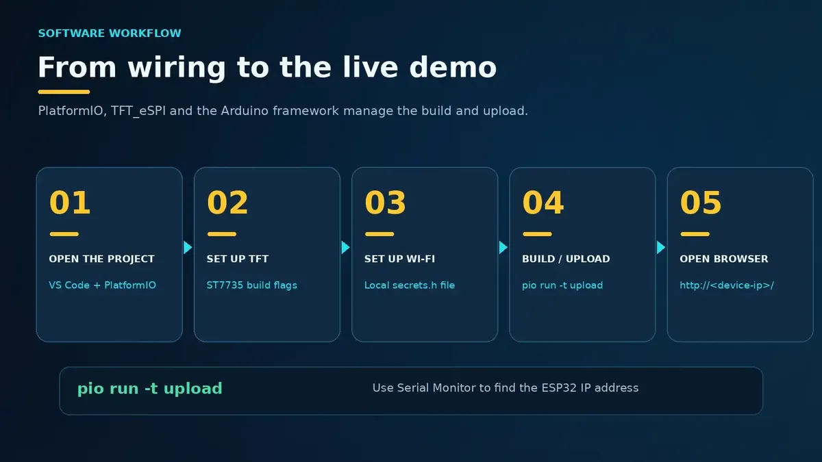
From the repository root in the VS Code PlatformIO terminal, run:
pio run -t uploadpio run -t upload
If PlatformIO does not select the intended serial port, inspect available ports in the IDE and configure the correct one. To view serial status messages:
pio device monitor -b 115200pio device monitor -b 115200
When Wi-Fi connects, look for the ESP32's local IP address in the serial output or on its screen. Open http://DEVICE_IP/ in a browser on the same local network, replacing DEVICE_IP with the actual address.
The firmware defines a GET /data endpoint for its visualization JSON and GET /health
for status checks. The browser dashboard will not be reachable from an unrelated Wi-Fi network without additional network configuration.
Test the result
Step 1
Power the ESP32-S3 with the TFT and microphone connected. Verify that the display initializes and shows the Spectra Studio graphics.
Step 2
Speak, clap or play music near the microphone. Verify that the waveform, bar heights and level indicators react to changing audio.
Step 3
Check Wi-Fi connection status and identify the IP address reported by the ESP32-S3.
Step 4
Open the local dashboard. Check that the spectrum, waveform and waterfall animations react to the same sound source.
Step 5
If needed, open /health and /data directly in the browser to distinguish a network problem from a UI rendering problem.
The video demonstrates a working local TFT visualizer and browser dashboard, but it does not establish independently measured FFT accuracy, metering calibration, frame rate under all conditions or suitability for audio instrumentation.
Troubleshooting
The TFT stays blank or displays incorrect colors
Check the 3.3 V supply, ground, CS/DC/RST and SPI GPIO mapping. Verify the specific ST7735 module's tab type, width, height, color order and backlight circuitry. A different breakout may need an adjusted TFT_eSPI configuration.
The microphone produces silence or erratic bars
Confirm I2S, not I2C, wiring: WS to GPIO4, SCK to GPIO5, SD to GPIO6 and L/R to GND. Check microphone supply voltage and whether the firmware reads the selected channel. Nearby noise, very low signal levels and inadequate grounding can affect the visual response.
Compilation fails with secrets.h not found
Create the local src/secrets.h as shown in the configuration section. Ensure it sits next to the src/main.cpp file and that WIFI_SSID and WIFI_PASSWORD are defined.
The visualizer runs but the browser cannot connect
Use the serial monitor to confirm a Wi-Fi connection and the current local IP. Check that the browser is on the same reachable network, try /health and ensure that client isolation or router firewall settings do not block local traffic. The published program attempts reconnection if Wi-Fi drops.
A screen or web view appears slow
Check Wi-Fi signal quality, the active browser's performance and firmware/display settings. The software targets roughly 30 display frames per second, but this is a design target rather than a guarantee for all hardware and network conditions.
Safety and limitations
- The ESP32-S3 GPIOs and INMP441 breakout are 3.3 V devices. Do not send 5 V signals to the input pins.
- Confirm that your specific TFT's backlight circuit tolerates the proposed 3.3 V wiring. Do not assume every breakout includes a current-limiting resistor.
- Use USB power appropriate for the ESP32-S3 board; disconnect power before changing wires.
- The audio indicators are for visual feedback; the example does not provide calibrated SPL, studio-grade dBFS measurement or an exact FFT spectrum.
- The browser server shown in the public code has no documented user authentication. Keep it on a trusted local network and do not forward port 80 to the internet.
- AI-generated code and connection diagrams still require engineering review and hardware testing.
Extending the project
Possible follow-up builds include adding a suitable LED strip with separate power and level shifting, adapting the design to a different display, housing the modules in a 3D-printed enclosure, or adding more responsive beat detection. Bluetooth audio would require a separately designed and tested input path; it is not part of the demonstrated INMP441 microphone build.