On This Page
Introduction
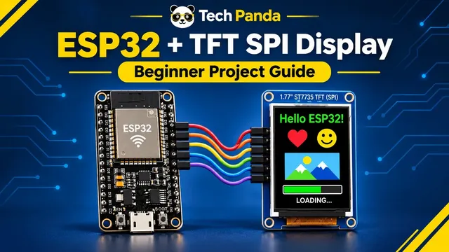
Want to connect a color TFT display to an ESP32 without manually writing an entire graphics program? This beginner-friendly project walks through wiring a 1.77-inch, 128 × 160 ST7735 SPI display to a classic ESP32 development board and preparing the firmware with Visual Studio Code, PlatformIO, and an AI coding agent.
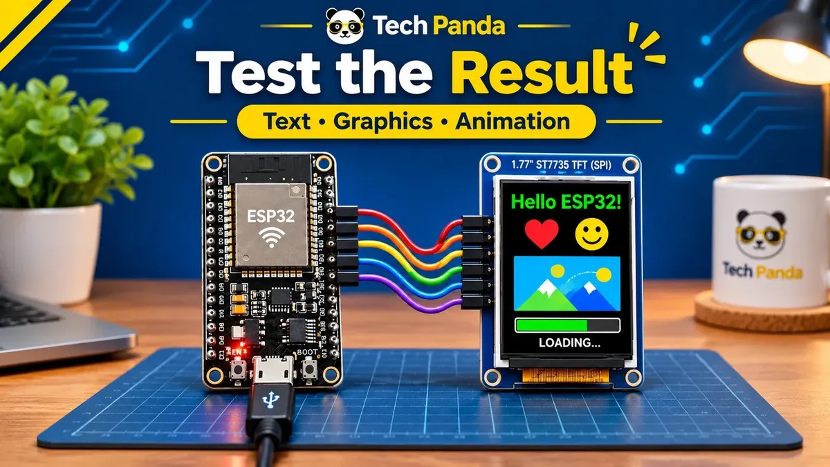
The finished demonstration shows “Hello ESP32!”, colorful shapes, a small illustrated scene, and a moving-circle animation. You will learn how the eight display pins work, which ESP32 GPIOs to use, how to generate a PlatformIO project with a coding agent, and how to upload firmware to the board.
No manual code writing is required to follow the video workflow, but you still need to verify the AI-generated wiring and firmware before uploading. A standalone example implementation is also included below; it is newly prepared for this article and has not been hardware-tested against the exact display used in the video.
What you will build
- An ESP32-controlled, full-color SPI TFT display.
- A small graphical screen containing text, shapes, an illustrated scene, and animation.
- A VS Code + PlatformIO workflow that can be extended into dashboards, sensor displays, or other small embedded interfaces.
What you will need
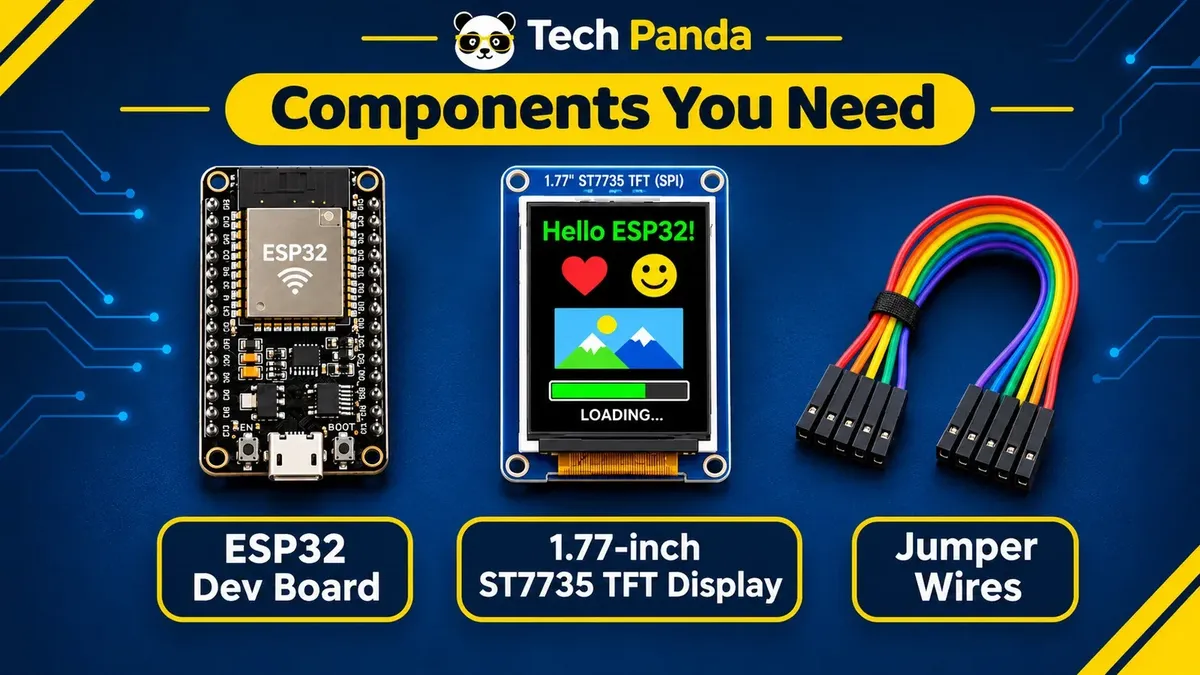
Components
| Qty | Component | Notes |
|---|---|---|
| 1 | ESP32 development board | Classic ESP32 DevKit / ESP32-WROOM-32 type, with GPIO 2, 4, 5, 18, 23, and 25 available |
| 1 | 1.77-inch ST7735 SPI TFT display | 128 × 160 pixels, eight-pin module with BLK, CS, DC, RST, SDA, SCL, VCC, and GND |
| 1 set | Jumper wires | Suitable for the connector/header type on your boards; approximately eight connections |
| 1 | USB data cable | Must support data transfer, not charging only |
| 1 | Computer | Windows, macOS, or Linux with VS Code and PlatformIO |
Software
- Visual Studio Code — code editor.
- PlatformIO IDE — ESP32 board setup, libraries, builds, uploads, and serial monitoring.
- An AI coding assistant integrated with VS Code, such as Codex — creates or updates the project from a written prompt.
- TFT_eSPI — Arduino-compatible display graphics library supporting the ST7735 controller.
Prerequisites
You should be comfortable identifying a pin label, connecting jumper wires, and plugging a development board into a computer. You do not need prior graphics programming experience. Install VS Code, the PlatformIO IDE extension, and your preferred AI coding agent before starting.
This specific GPIO mapping and sample configuration target a classic ESP32, not an ESP32-C3, ESP32-C6, or another board with different available pins. Check the exact pin labels on your board.
How the display works
The ST7735 is the controller inside many small color TFT modules. The ESP32 sends commands and pixel data using SPI (Serial Peripheral Interface). SPI reduces the number of wires required compared with parallel TFT interfaces.
On the display used in the video, SCL is the SPI clock signal and SDA is the SPI data input (MOSI); this SDA is not I²C SDA. The ESP32 also controls CS to select the display, DC to distinguish commands from graphics data, and RST to reset the controller. BLK controls the backlight on modules that expose it.
The display resolution is 128 pixels wide by 160 pixels high in portrait mode. The TFT_eSPI library handles the low-level ST7735 commands, so your application can use functions for text, lines, rectangles, circles, and other graphics.
Understanding the display pins
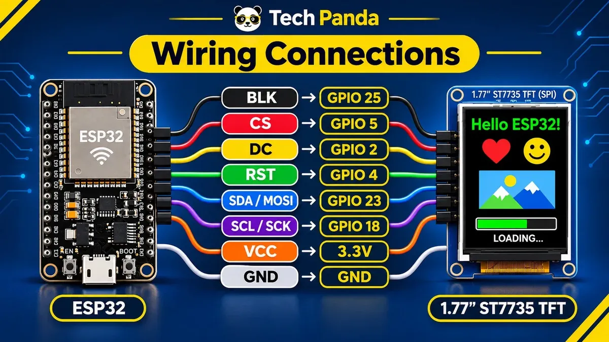
| Pin | Signal | Notes |
|---|---|---|
| GND | GND | Common electrical ground |
| VCC | 3.3V | Supply voltage for the 3.3V module shown; verify your module specification |
| SCL / SCK | GPIO 18 | SPI clock |
| SDA / MOSI | GPIO 23 | ESP32-to-display SPI data |
| RST / RES | GPIO 4 | Display reset |
| DC / A0 | GPIO 2 | Data/command select |
| CS | GPIO 5 | Chip select |
| BLK / LED | GPIO 25 | Backlight control if the module accepts a 3.3V GPIO control signal |
Important: The label order on a module can vary. Follow its printed labels and datasheet rather than counting pins from the left or right. Do not apply 5V to a display specified for 3.3V. GPIO 2 and GPIO 5 are ESP32 boot-strapping pins; avoid external circuitry that forces incompatible startup levels.
If you do not need brightness control, the video also describes connecting BLK to 3.3V, but only when the display module is designed for that connection. Verify the module's backlight circuit before powering it.
Assembly and hardware wiring
Step 1
Disconnect USB power. Set the ESP32 and TFT on a non-conductive surface, and identify all eight module pins by their silkscreen labels.
Step 2
Connect power. Connect display VCC to ESP32 3.3V and GND to GND. Do not substitute the ESP32 5V/VIN header.
Step 3
Connect SPI. Wire SCL to GPIO 18 and SDA to GPIO 23. These carry clock and display data.
Step 4
Connect display control. Wire RST to GPIO 4, DC to GPIO 2, and CS to GPIO 5.
Step 5
Connect the backlight. Use GPIO 25 only if your module's BLK input is compatible with direct 3.3V logic control; otherwise follow the module's backlight requirements.
Step 6
Inspect every wire. Confirm there are no short circuits, reversed power pins, or loose connections before connecting USB.
Set up PlatformIO in VS Code
Step 1
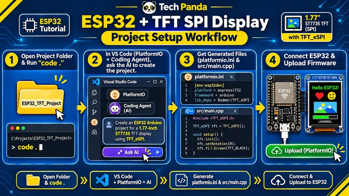
Create an empty folder, for example ESP32_ST7735_TFT.
Step 2
Open a terminal in that folder and run "code ." to open the current folder in VS Code. If the command is unavailable, open the folder through File → Open Folder.
Step 3
Open Extensions and install PlatformIO IDE.
Step 4
Install and open an AI coding agent extension that you trust.
Step 5
Confirm your board model and USB driver are recognized by the computer. Some ESP32 boards need a USB-to-serial driver for their USB-UART chip.
Generate the project with an AI coding agent
Paste the following prompt into your VS Code coding assistant. It includes the exact display connections used in the tutorial and asks the assistant to generate both files.
Create a complete PlatformIO project for a classic ESP32 DevKit using the Arduino framework and Bodmer's TFT_eSPI library. Hardware: - 1.77-inch, 128x160 ST7735 SPI TFT display - Display VCC: 3.3V; GND: GND - SCL/SCK: GPIO18 - SDA/MOSI: GPIO23 - RST: GPIO4 - DC/A0: GPIO2 - CS: GPIO5 - BLK: GPIO25, active-high only if the module supports it Requirements: 1. Generate platformio.ini and src/main.cpp. 2. Use the esp32dev PlatformIO board and Arduino framework. 3. Configure the ST7735 driver, resolution, SPI pins, and an appropriate ST7735 panel initialization variant. 4. Put TFT_eSPI display setup flags in platformio.ini; do not modify installed library files. 5. Initialize the screen and print "Hello ESP32!". 6. Draw colorful shapes, a small landscape illustration, a progress indicator, and a moving-circle animation. 7. Avoid unnecessary full-screen redrawing in the loop. 8. Include serial diagnostics and concise comments. 9. Explain how to build, upload, and troubleshoot blank screens, wrong colors, offsets, and USB upload failures. 10. Do not claim the result is hardware-tested. Before generating code, state assumptions about the ESP32 board and the ST7735 module variant.Create a complete PlatformIO project for a classic ESP32 DevKit using the Arduino framework and Bodmer's TFT_eSPI library. Hardware: - 1.77-inch, 128x160 ST7735 SPI TFT display - Display VCC: 3.3V; GND: GND - SCL/SCK: GPIO18 - SDA/MOSI: GPIO23 - RST: GPIO4 - DC/A0: GPIO2 - CS: GPIO5 - BLK: GPIO25, active-high only if the module supports it Requirements: 1. Generate platformio.ini and src/main.cpp. 2. Use the esp32dev PlatformIO board and Arduino framework. 3. Configure the ST7735 driver, resolution, SPI pins, and an appropriate ST7735 panel initialization variant. 4. Put TFT_eSPI display setup flags in platformio.ini; do not modify installed library files. 5. Initialize the screen and print "Hello ESP32!". 6. Draw colorful shapes, a small landscape illustration, a progress indicator, and a moving-circle animation. 7. Avoid unnecessary full-screen redrawing in the loop. 8. Include serial diagnostics and concise comments. 9. Explain how to build, upload, and troubleshoot blank screens, wrong colors, offsets, and USB upload failures. 10. Do not claim the result is hardware-tested. Before generating code, state assumptions about the ESP32 board and the ST7735 module variant.
An AI agent can prepare and revise files, but it cannot guarantee that your particular display uses the same ST7735 variant or that the firmware will work without physical testing.
Project configuration
A PlatformIO project normally contains a platformio.ini configuration file and a src/main.cpp Arduino program. The following is a reference configuration, not a copy of the video's original generated files. The ST7735_GREENTAB option is an initial assumption; modules with different offsets or color ordering may need a different variant.
; Example project for a classic ESP32 DevKit and 128x160 ST7735 SPI TFT. ; Review the display's exact controller, tab variant, and board pinout. [env:esp32dev] platform = espressif32 board = esp32dev framework = arduino monitor_speed = 115200 lib_deps = bodmer/TFT_eSPI build_flags = -D USER_SETUP_LOADED=1 -D ST7735_DRIVER=1 -D ST7735_GREENTAB=1 -D TFT_WIDTH=128 -D TFT_HEIGHT=160 -D TFT_MOSI=23 -D TFT_SCLK=18 -D TFT_MISO=-1 -D TFT_CS=5 -D TFT_DC=2 -D TFT_RST=4 -D LOAD_GLCD=1 -D LOAD_FONT2=1 -D SPI_FREQUENCY=27000000; Example project for a classic ESP32 DevKit and 128x160 ST7735 SPI TFT. ; Review the display's exact controller, tab variant, and board pinout. [env:esp32dev] platform = espressif32 board = esp32dev framework = arduino monitor_speed = 115200 lib_deps = bodmer/TFT_eSPI build_flags = -D USER_SETUP_LOADED=1 -D ST7735_DRIVER=1 -D ST7735_GREENTAB=1 -D TFT_WIDTH=128 -D TFT_HEIGHT=160 -D TFT_MOSI=23 -D TFT_SCLK=18 -D TFT_MISO=-1 -D TFT_CS=5 -D TFT_DC=2 -D TFT_RST=4 -D LOAD_GLCD=1 -D LOAD_FONT2=1 -D SPI_FREQUENCY=27000000
The USER_SETUP_LOADED build flag instructs TFT_eSPI to use the settings supplied by your project instead of a default library setup. The esp32dev board identifier is suitable only for compatible classic ESP32 development boards. Adjust the board and display configuration to your hardware.
Example ESP32 source code
This independent example demonstrates the requested behavior. It shows greeting text, colorful shapes, a simple scene, a progress bar, and a bouncing circle. It has not been compiled or electrically verified on the specific tutorial hardware.
// Tech Panda example: ESP32 DevKit + 1.77-inch ST7735 128x160 TFT // Example based on the supplied tutorial, NOT a copy of its original source. // Requires a compatible display and matching platformio.ini settings. #include <Arduino.h> #include <TFT_eSPI.h> constexpr int BACKLIGHT_PIN = 25; constexpr int SCREEN_WIDTH = 128; constexpr int SCREEN_HEIGHT = 160; TFT_eSPI tft = TFT_eSPI(); int ballX = 12; int ballDirection = 1; unsigned long lastFrameMs = 0; void drawDemoScreen() { tft.fillScreen(TFT_BLACK); tft.setTextColor(TFT_GREEN, TFT_BLACK); tft.drawCentreString("Hello ESP32!", SCREEN_WIDTH / 2, 8, 2); // Red heart: two circles and one triangle. tft.fillCircle(29, 44, 10, TFT_RED); tft.fillCircle(45, 44, 10, TFT_RED); tft.fillTriangle(19, 48, 55, 48, 37, 67, TFT_RED); // Yellow smiley. tft.fillCircle(93, 49, 17, TFT_YELLOW); tft.fillCircle(87, 45, 2, TFT_BLACK); tft.fillCircle(99, 45, 2, TFT_BLACK); tft.drawLine(85, 56, 90, 60, TFT_BLACK); tft.drawLine(90, 60, 96, 60, TFT_BLACK); tft.drawLine(96, 60, 102, 55, TFT_BLACK); // Small image built from graphics primitives. tft.fillRect(15, 77, 98, 35, TFT_CYAN); tft.fillCircle(89, 86, 6, TFT_YELLOW); tft.fillTriangle(15, 112, 49, 84, 79, 112, TFT_GREEN); tft.fillTriangle(51, 112, 85, 79, 113, 112, TFT_BLUE); tft.fillTriangle(43, 89, 49, 84, 56, 91, TFT_WHITE); tft.fillTriangle(78, 86, 85, 79, 92, 87, TFT_WHITE); // Simple progress bar. tft.drawRoundRect(15, 119, 98, 12, 2, TFT_WHITE); tft.fillRect(18, 122, 51, 6, TFT_GREEN); tft.setTextColor(TFT_WHITE, TFT_BLACK); tft.drawCentreString("Animated demo", SCREEN_WIDTH / 2, 134, 1); } void setup() { Serial.begin(115200); pinMode(BACKLIGHT_PIN, OUTPUT); digitalWrite(BACKLIGHT_PIN, HIGH); // For active-high BLK inputs only. tft.init(); tft.setRotation(0); // Portrait: 128x160 for most 1.77-inch modules. drawDemoScreen(); Serial.println("ST7735 display demo started"); } void loop() { if (millis() - lastFrameMs < 20) return; lastFrameMs = millis(); // Redraw only the animation area to reduce flicker. tft.fillRect(0, 144, SCREEN_WIDTH, 16, TFT_BLACK); tft.fillCircle(ballX, 152, 4, TFT_CYAN); ballX += ballDirection * 2; if (ballX >= 120 || ballX <= 8) ballDirection = -ballDirection; }// Tech Panda example: ESP32 DevKit + 1.77-inch ST7735 128x160 TFT // Example based on the supplied tutorial, NOT a copy of its original source. // Requires a compatible display and matching platformio.ini settings. #include <Arduino.h> #include <TFT_eSPI.h> constexpr int BACKLIGHT_PIN = 25; constexpr int SCREEN_WIDTH = 128; constexpr int SCREEN_HEIGHT = 160; TFT_eSPI tft = TFT_eSPI(); int ballX = 12; int ballDirection = 1; unsigned long lastFrameMs = 0; void drawDemoScreen() { tft.fillScreen(TFT_BLACK); tft.setTextColor(TFT_GREEN, TFT_BLACK); tft.drawCentreString("Hello ESP32!", SCREEN_WIDTH / 2, 8, 2); // Red heart: two circles and one triangle. tft.fillCircle(29, 44, 10, TFT_RED); tft.fillCircle(45, 44, 10, TFT_RED); tft.fillTriangle(19, 48, 55, 48, 37, 67, TFT_RED); // Yellow smiley. tft.fillCircle(93, 49, 17, TFT_YELLOW); tft.fillCircle(87, 45, 2, TFT_BLACK); tft.fillCircle(99, 45, 2, TFT_BLACK); tft.drawLine(85, 56, 90, 60, TFT_BLACK); tft.drawLine(90, 60, 96, 60, TFT_BLACK); tft.drawLine(96, 60, 102, 55, TFT_BLACK); // Small image built from graphics primitives. tft.fillRect(15, 77, 98, 35, TFT_CYAN); tft.fillCircle(89, 86, 6, TFT_YELLOW); tft.fillTriangle(15, 112, 49, 84, 79, 112, TFT_GREEN); tft.fillTriangle(51, 112, 85, 79, 113, 112, TFT_BLUE); tft.fillTriangle(43, 89, 49, 84, 56, 91, TFT_WHITE); tft.fillTriangle(78, 86, 85, 79, 92, 87, TFT_WHITE); // Simple progress bar. tft.drawRoundRect(15, 119, 98, 12, 2, TFT_WHITE); tft.fillRect(18, 122, 51, 6, TFT_GREEN); tft.setTextColor(TFT_WHITE, TFT_BLACK); tft.drawCentreString("Animated demo", SCREEN_WIDTH / 2, 134, 1); } void setup() { Serial.begin(115200); pinMode(BACKLIGHT_PIN, OUTPUT); digitalWrite(BACKLIGHT_PIN, HIGH); // For active-high BLK inputs only. tft.init(); tft.setRotation(0); // Portrait: 128x160 for most 1.77-inch modules. drawDemoScreen(); Serial.println("ST7735 display demo started"); } void loop() { if (millis() - lastFrameMs < 20) return; lastFrameMs = millis(); // Redraw only the animation area to reduce flicker. tft.fillRect(0, 144, SCREEN_WIDTH, 16, TFT_BLACK); tft.fillCircle(ballX, 152, 4, TFT_CYAN); ballX += ballDirection * 2; if (ballX >= 120 || ballX <= 8) ballDirection = -ballDirection; }
Save this code as src/main.cpp. If you use your AI agent's generated code instead, compare its GPIO assignments against the wiring table before uploading.
Build and upload the firmware
Step 1
Connect the ESP32 to the computer using a USB data cable.
Step 2
In VS Code, open PlatformIO and verify that the USB serial device is detected.
Step 3
Use PlatformIO: Build to compile the firmware and check for errors.
Step 4
Click the Upload control in PlatformIO, or run "pio run -t upload" in a configured PlatformIO terminal.
Step 5
If an older ESP32 board cannot enter download mode automatically, hold BOOT as flashing begins and release it once the upload starts. Do this only if required.
Step 6
Open the serial monitor at 115200 baud if you need diagnostic output.
Upload shortcuts may differ by OS and PlatformIO version. The PlatformIO upload control is more reliable than relying on a keyboard shortcut mentioned in a video.
Test the result
After a successful upload, the TFT should initialize and show a colored demonstration. Look for the “Hello ESP32!” greeting at the top, graphics in the center, a loading-style bar, and a small circle moving across the lower screen area.
The video shows the same general sequence: connect the board, detect its serial port, flash the firmware, and observe the display. The particular layout depends on which code was generated or used.
If your screen works but appears rotated, use tft.setRotation(0) through tft.setRotation(3) as appropriate. If the graphics are offset or the colors appear incorrect, review the ST7735 tab/initialization variant and RGB/BGR order in TFT_eSPI rather than changing wiring at random.
Troubleshooting
- The screen stays black: Check VCC, GND, backlight voltage requirements, and whether the correct display driver was selected. If the backlight is on but no image appears, inspect SCL, SDA/MOSI, CS, DC, and RST.
- The upload cannot connect: Check the USB cable, serial port, USB-UART driver, and whether another program has opened the port. Try the ESP32 BOOT-button procedure if necessary.
- The screen is white or shows garbage: Confirm the ST7735 controller, correct SPI GPIOs, and the module's initialization variant. Test a lower SPI frequency if communication is unreliable.
- Colors look swapped or the image is shifted: Different ST7735 panels may require a different tab setting or RGB/BGR selection.
- The display is rotated: Adjust tft.setRotation() and ensure the code's dimensions match the chosen orientation.
- The backlight does not respond to GPIO 25: Check whether BLK is active-high, active-low, always-on, or driven by a transistor on your exact module. Do not drive an unverified LED load directly from an ESP32 GPIO.
- The ESP32 does not boot: Check wiring connected to boot-strapping pins, especially GPIO 2 and GPIO 5, and remove circuits that hold those pins at unsuitable levels during reset.
- The animation flickers: Draw only the region that changes, reduce unnecessary screen clears, or lower the frame rate.
Safety and limitations
- The tutorial is for a 3.3V supply and 3.3V SPI logic. Check your display's actual voltage specification before connecting power.
- Confirm the backlight electrical load before connecting it directly to a GPIO; some boards need a transistor or have an onboard resistor/driver.
- Never rewire while powered. Avoid shorts between 3.3V and GND.
- The example assumes a classic ESP32 and an ST7735 variant; other ESP32 families and ST7735 modules may require different GPIOs or settings.
- AI-generated source code can contain incorrect pin definitions, library APIs, or unsafe assumptions. Review it and test with hardware.
- The generated editorial images illustrate the project, but are not authoritative pinout diagrams. Use the pin table and module silkscreen for wiring.
Extending the project
Once the basic display works, try adding a Wi-Fi connection indicator, sensor readings, a mini weather display, a stopwatch, or progress and status graphics. To show real photo files or advanced images, you need additional image conversion, storage, and rendering code; the introductory shapes demo does not by itself implement arbitrary image-file display.