On This Page
Introduction
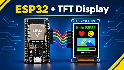
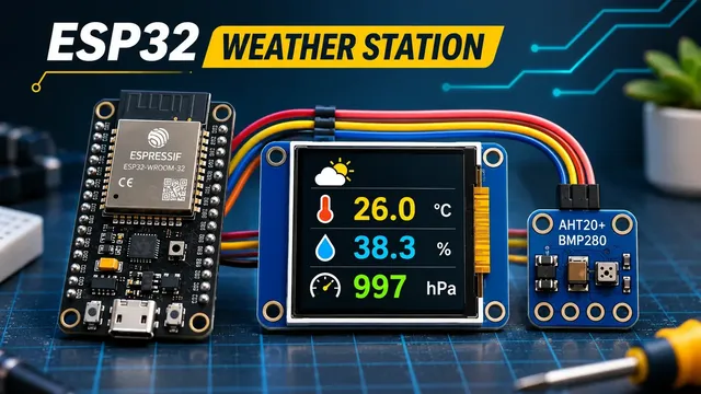
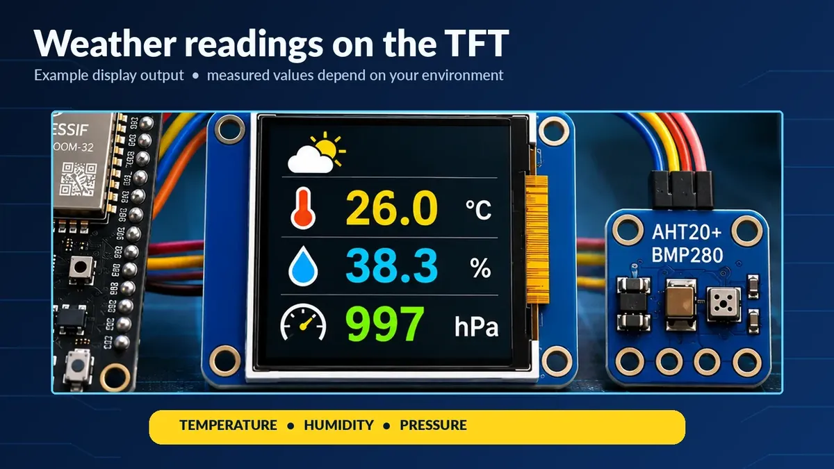
This project turns a classic ESP32 development board into a compact indoor weather monitor. A combined AHT20 + BMP280 module measures temperature, relative humidity, and air pressure; the ESP32 reads the sensors over I2C and draws the results on a 1.77-inch, 128 × 160 ST7735 TFT display over SPI.
The build shown in the video uses Visual Studio Code, PlatformIO, and an AI coding assistant to generate the firmware rather than writing the initial project manually. The finished demonstration shows three live sensor readings on a color dashboard. This is a local sensor monitor, not an internet weather forecast.
What you will build
The TFT shows temperature in degrees Celsius (°C), humidity in percent relative humidity (% RH), and local atmospheric pressure in hectopascals (hPa). The example dashboard in the video uses contrasting colors, icons, and separate reading areas. Values will vary with the actual environment; the readings shown in promotional images are illustrative, not measurements you should expect to reproduce.
The guide covers the physical connections, the difference between SPI and I2C, PlatformIO setup, the prompt given to the AI assistant, uploading firmware, and checks to make when the screen or sensors do not respond.
What you will need
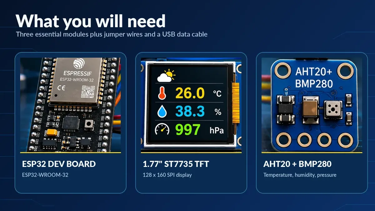
Components
| Qty | Component | Notes |
|---|---|---|
| 1 | ESP32 development board | Classic ESP32 DevKit / ESP32-WROOM-32; GPIO numbers below assume this family |
| 1 | 1.77-inch ST7735 SPI TFT display | 128 × 160 pixels, eight-pin module; verify your board's pin labels and voltage requirements |
| 1 | AHT20 + BMP280 sensor module | Combined temperature, humidity and pressure breakout, using I2C |
| 1 set | Jumper wires | Suitable length and male/female ends for the modules |
| 1 | USB data cable | Must support data, not charging only |
Software
- Visual Studio Code — the editor used to open the project folder.
- PlatformIO IDE — builds, uploads, and monitors the ESP32 firmware.
- A VS Code AI coding assistant, such as Codex, for creating and refining the project files.
- TFT_eSPI — driver and drawing functions for the ST7735 display.
- Adafruit AHTX0 and Adafruit BMP280 — example sensor libraries for the separately supplied reference firmware.
Prerequisites
Use a classic ESP32 board that exposes the listed GPIOs. Check that the sensor breakout and TFT breakout accept 3.3 V power and 3.3 V logic. Install VS Code with PlatformIO and an AI coding assistant. A working USB data cable and a computer with permission to access the USB serial port are required.
The video presents AI-assisted coding as the workflow. You still need to inspect the generated pin configuration, library dependencies, and compile errors before flashing firmware.
How it works
Two different buses operate simultaneously on the ESP32:
- SPI connects the ST7735 TFT. The ESP32 sends display commands and pixels using SCK (clock) and MOSI (data). CS selects the display, DC distinguishes commands from data, RST resets it, and BLK controls backlight on compatible modules.
- I2C connects the combined weather sensor. SDA carries bidirectional data and SCL provides the clock. AHT20 supplies temperature and humidity; BMP280 supplies barometric pressure.
The signals named SDA and SCL appear on both modules, but they mean different things here. On this particular TFT, SDA is its SPI MOSI input and SCL is its SPI clock. On the sensor breakout, SDA/SCL refer to I2C. These must connect to their separately specified ESP32 pins, not to one another.
Pressure in hPa is the sensor's local air pressure. It is not automatically corrected to sea-level pressure, and the BMP280 does not measure humidity.
Wiring and connections
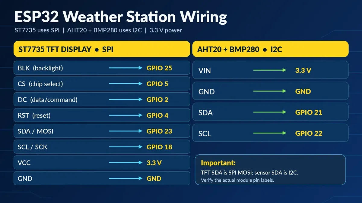
Turn off USB power before adding or moving jumper wires. Refer to the printed labels on your specific PCB rather than assuming every ST7735 module has the same physical pin order.
ST7735 display to ESP32 — SPI
Pin | Signal | Notes
TFT BLK | ESP32 GPIO 25 | Backlight control, **only if BLK is a compatible logic-level input**
TFT CS | ESP32 GPIO 5 | SPI chip select
TFT DC | ESP32 GPIO 2 | Command/data select; GPIO 2 is a boot-strapping pin
TFT RST | ESP32 GPIO 4 | Display reset
TFT SDA / MOSI | ESP32 GPIO 23 | SPI data from ESP32 to display
TFT SCL / SCK | ESP32 GPIO 18 | SPI clock
TFT VCC | ESP32 3.3 V | Verify module supply specification; do not assume 5 V compatibility
TFT GND | ESP32 GND | Common ground
AHT20 + BMP280 module to ESP32 — I2C
| Pin | Signal | Notes |
|---|---|---|
| Sensor VIN | ESP32 3.3 V | Power input for the combined breakout, subject to its stated rating |
| Sensor GND | ESP32 GND | Common ground |
| Sensor SDA | ESP32 GPIO 21 | I2C data, not TFT MOSI |
| Sensor SCL | ESP32 GPIO 22 | I2C clock, not TFT SCK |
All grounds must be common. GPIO 2 and GPIO 5 have ESP32 boot-strapping roles, so attached peripheral circuits can affect boot or flashing if they drive these pins into unsuitable states.
Assemble the hardware
Step 1
Disconnect the ESP32 from USB. Identify the display's eight pins and the sensor breakout's four pins. Confirm which side of each board is marked VCC/VIN and GND.
Step 2
Wire the TFT. Connect the SPI lines to GPIO 18 and 23, then CS to GPIO 5, DC to GPIO 2, RST to GPIO 4, 3.3 V to VCC, and ground to GND.
Step 3
Connect the backlight safely. Follow the video mapping of BLK to GPIO 25 only if the module accepts a 3.3 V logic signal at that pin. If BLK powers an exposed LED directly, use an appropriate current-limited driver instead.
Step 4
Wire the sensor. Connect I2C SDA to GPIO 21, I2C SCL to GPIO 22, and supply 3.3 V and GND.
Step 5
Check the wiring again. Inspect for offset header connections, reversed power polarity, stray strands, and loose jumpers before applying USB power.
Set up PlatformIO and VS Code
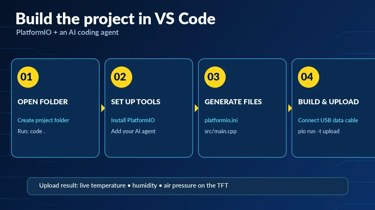
Create a folder for the project. Open a terminal in that folder and run:
code .code .
The space before the period matters. code .
tells Visual Studio Code to open the current directory. If the code command is unavailable, open the folder through VS Code's File → Open Folder option.
Install the PlatformIO IDE extension and your preferred AI coding assistant. Open the assistant's chat inside VS Code, with the new folder as the workspace.
AI coding prompt
The following copy-and-paste prompt is reconstructed from the requirements demonstrated in the video. It explicitly separates the two hardware buses and requests the correct PlatformIO filenames.
Create a complete PlatformIO project for an ESP32 DevKit using the Arduino framework. Hardware: - 1.77-inch ST7735 TFT SPI display, 128 x 160 pixels - Combined AHT20 + BMP280 I2C temperature/humidity/pressure module TFT connections (SPI): BLK -> GPIO25 (backlight control only if the module supports it) CS -> GPIO5 DC -> GPIO2 RST -> GPIO4 MOSI / TFT SDA -> GPIO23 SCK / TFT SCL -> GPIO18 VCC -> 3.3V GND -> GND Sensor connections (I2C): VIN -> 3.3V GND -> GND SDA -> GPIO21 SCL -> GPIO22 Use TFT_eSPI for the display. Select appropriate Arduino libraries for AHT20 and BMP280, and handle common BMP280 I2C addresses 0x76/0x77. Create platformio.ini and src/main.cpp. Show live temperature in degrees Celsius, relative humidity in percent, and local air pressure in hPa. Create an uncluttered dashboard suited to 128 x 160 pixels: black background, large legible colored values, and distinct reading areas. Refresh without excessive flicker, report missing sensors in Serial Monitor, and display an error state if a sensor is unavailable. Explain which ST7735 initialization/tab variant is configured and how to change it if colors or offsets are wrong. Compile and fix any build errors. Do not claim physical hardware verification unless I confirm the result.Create a complete PlatformIO project for an ESP32 DevKit using the Arduino framework. Hardware: - 1.77-inch ST7735 TFT SPI display, 128 x 160 pixels - Combined AHT20 + BMP280 I2C temperature/humidity/pressure module TFT connections (SPI): BLK -> GPIO25 (backlight control only if the module supports it) CS -> GPIO5 DC -> GPIO2 RST -> GPIO4 MOSI / TFT SDA -> GPIO23 SCK / TFT SCL -> GPIO18 VCC -> 3.3V GND -> GND Sensor connections (I2C): VIN -> 3.3V GND -> GND SDA -> GPIO21 SCL -> GPIO22 Use TFT_eSPI for the display. Select appropriate Arduino libraries for AHT20 and BMP280, and handle common BMP280 I2C addresses 0x76/0x77. Create platformio.ini and src/main.cpp. Show live temperature in degrees Celsius, relative humidity in percent, and local air pressure in hPa. Create an uncluttered dashboard suited to 128 x 160 pixels: black background, large legible colored values, and distinct reading areas. Refresh without excessive flicker, report missing sensors in Serial Monitor, and display an error state if a sensor is unavailable. Explain which ST7735 initialization/tab variant is configured and how to change it if colors or offsets are wrong. Compile and fix any build errors. Do not claim physical hardware verification unless I confirm the result.
After the agent generates the files, review the GPIO definitions and package dependencies. The transcription calls the configuration platformio.pio; the actual required filename is platformio.ini. Likewise, the application source belongs in src/main.cpp.
Reference PlatformIO configuration
This is a newly authored example, not the original platformio.ini used in the video, and it has not been compiled or physically tested as part of this article. Its board target assumes a classic esp32dev board. For other boards, select the matching PlatformIO environment.
[env:esp32dev] platform = espressif32 board = esp32dev framework = arduino monitor_speed = 115200 lib_deps = bodmer/TFT_eSPI adafruit/Adafruit AHTX0 adafruit/Adafruit BMP280 Library adafruit/Adafruit Unified Sensor adafruit/Adafruit BusIO build_flags = -D USER_SETUP_LOADED=1 -D ST7735_DRIVER=1 -D ST7735_BLACKTAB=1 -D TFT_WIDTH=128 -D TFT_HEIGHT=160 -D TFT_MISO=-1 -D TFT_MOSI=23 -D TFT_SCLK=18 -D TFT_CS=5 -D TFT_DC=2 -D TFT_RST=4 -D LOAD_GLCD=1 -D LOAD_FONT2=1 -D LOAD_FONT4=1 -D SPI_FREQUENCY=16000000[env:esp32dev] platform = espressif32 board = esp32dev framework = arduino monitor_speed = 115200 lib_deps = bodmer/TFT_eSPI adafruit/Adafruit AHTX0 adafruit/Adafruit BMP280 Library adafruit/Adafruit Unified Sensor adafruit/Adafruit BusIO build_flags = -D USER_SETUP_LOADED=1 -D ST7735_DRIVER=1 -D ST7735_BLACKTAB=1 -D TFT_WIDTH=128 -D TFT_HEIGHT=160 -D TFT_MISO=-1 -D TFT_MOSI=23 -D TFT_SCLK=18 -D TFT_CS=5 -D TFT_DC=2 -D TFT_RST=4 -D LOAD_GLCD=1 -D LOAD_FONT2=1 -D LOAD_FONT4=1 -D SPI_FREQUENCY=16000000
USER_SETUP_LOADED prevents the library's default pin setup from overriding the settings in platformio.ini. ST7735_BLACKTAB is only a starting variant; some 128 × 160 displays need ST7735_GREENTAB or ST7735_REDTAB instead. Try one variant at a time if the display is offset, inverted, or has incorrect colors. A faster SPI clock may work with short, reliable wires, but the example uses 16 MHz as a conservative initial setting.
Reference ESP32 firmware
The ZIP includes firmware/src/main.cpp, an independently authored example that reads an AHT20 and BMP280 with the Adafruit libraries, sends diagnostics to Serial Monitor, and draws a compact three-row display. It is not a copy of the video's generated firmware and has not been hardware-tested. Review and compile it before treating it as a verified build.
The complete source is supplied in the package alongside firmware/platformio.ini. Its core reading sequence is:
sensors_event_t humidity; sensors_event_t temperature; if (aht.getEvent(&humidity, &temperature)) { float tempC = temperature.temperature; float humidityRH = humidity.relative_humidity; // Present these readings on the TFT. } float localPressureHpa = bmp.readPressure() / 100.0f; // Convert Pa to hPa before presenting air pressure.sensors_event_t humidity; sensors_event_t temperature; if (aht.getEvent(&humidity, &temperature)) { float tempC = temperature.temperature; float humidityRH = humidity.relative_humidity; // Present these readings on the TFT. } float localPressureHpa = bmp.readPressure() / 100.0f; // Convert Pa to hPa before presenting air pressure.
The sample uses Wire.begin(21, 22) for I2C and initializes the BMP280 at 0x76, with 0x77
as a fallback. The AHT20 commonly uses I2C address 0x38. These addresses help diagnose an unresponsive sensor module; run an I2C scanner if neither device is detected.
Build and upload
With the project folder open in VS Code and a USB data cable connected to the ESP32, use the PlatformIO upload action or open the terminal and run:
pio run -t uploadpio run -t upload
PlatformIO compiles the code and uploads the firmware. If pio is not recognized by the terminal, use the extension's Upload control or enable the PlatformIO Core command line.
If the terminal remains at Connecting, some classic ESP32 boards require holding BOOT while upload begins, then releasing it once writing starts. Do not force buttons on a board already flashing successfully.
To read the diagnostics:
pio device monitor -b 115200pio device monitor -b 115200
Some boards expose a different serial port after reconnecting. Check PlatformIO's detected device list or set an appropriate upload port if required.
Test the result
On a working build, the ST7735 should light up and show temperature, relative humidity, and barometric pressure. Small changes in room conditions should eventually appear in the readings. In the reference firmware, values refresh every two seconds; the video's original firmware may use a different interval.
Check three independent behaviors:
- The display initializes with readable colors, correct orientation, and no obvious pixel offset.
- The AHT20 produces both temperature and humidity readings, not Sensor N/A.
- The BMP280 produces a plausible local pressure in hPa, not zero or Sensor N/A.
For sensor faults, consult the 115200-baud Serial Monitor before changing the TFT code. The video confirms a working demo, but the exact original compiled source and specific module revisions were not supplied with this article.
Troubleshooting
- TFT stays black: Check 3.3 V and ground, the backlight circuit, CS/DC/RST wiring, and the selected ST7735 variant. A lit backlight alone does not prove SPI data is reaching the display.
- Image shifted, inverted, or wrong colors: Change one ST7735 tab variant at a time (BLACKTAB, GREENTAB, REDTAB) and verify the declared width and height. Do not alter physical wires to compensate for a software offset.
- Temperature and humidity are missing: Verify sensor VIN/GND and I2C SDA/SCL on GPIO 21/22. Confirm the module contains an AHT20 and that an I2C scan shows the device.
- Pressure is missing: The BMP280 may use address 0x76 or 0x77. If the device is a BME280 or another variant, the BMP280 library's chip-ID check can fail.
- Upload stalls at Connecting: Confirm the USB cable carries data, close any serial monitor holding the port, choose the correct ESP32 target, and use BOOT only when necessary.
- ESP32 fails to boot after wiring: GPIO 2 and GPIO 5 are strapping pins on classic ESP32. Disconnect the peripheral temporarily to isolate any boot-level conflict before changing the GPIO plan.
- Display refresh flickers: Redraw only the reading areas or use a small sprite/buffer rather than clearing the entire screen on every update.
- Readings differ from a weather website: This module measures the conditions where it is installed. Pressure is local/station pressure rather than a sea-level-corrected forecast value.
Safety and limitations
Use the exact voltage rating of your purchased breakout boards. The configuration here expects 3.3 V logic and a shared ground. Never apply 5 V directly to a bare ST7735 controller or an ESP32 GPIO. Some TFT modules support 5 V on a regulated VIN; that cannot be inferred merely from the ST7735 chip name.
The BLK connection to GPIO 25 assumes the breakout has a suitable backlight control input. If it directly feeds a raw LED or exceeds an ESP32 output pin's current capability, use a suitable resistor/transistor driver circuit instead.
This is an indoor/local environmental display. Do not use it as a calibrated weather instrument, a safety alarm, or a substitute for certified measurements. The example source is an independently authored reference and is untested on the physical hardware.
Possible extensions
The video suggests adding animated icons, historical graphs, color themes, Wi-Fi weather updates, or a clock. Those features are ideas for a later software revision; they are not part of the demonstrated sensor-only firmware or the supplied reference example.