On This Page
Introduction
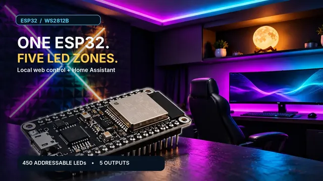
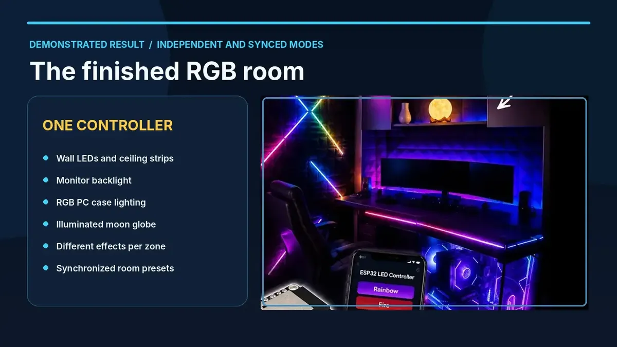
A single ESP32 can control several addressable LED installations without treating the whole room as one long strip. In this project, five independent WS2812B data outputs run lighting for the wall, monitor, PC case, ceiling and a moon globe. The demonstrated configuration uses 450 LEDs in total, with local browser control and Home Assistant integration.
The controller hosts its own interface at http://rgb.local
when the local network supports mDNS. FastLED renders animations, LittleFS stores the browser interface, and a local HTTP/JSON API lets other software change the lights. The video demonstrates independent zone settings as well as synchronized effects.
What you will build
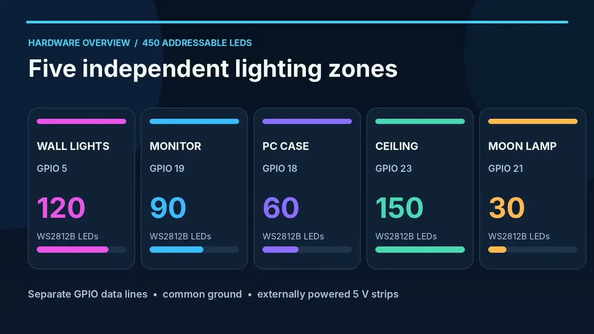
You will connect five WS2812B LED zones to one ESP32 and run a separate animation state for each zone. From the web interface, you can turn a zone on or off, choose colors and patterns, or adjust brightness. The example also connects Home Assistant to the controller through its REST API.
The five-zone layout matters: a monitor strip does not have to display the same color as a ceiling strip. The demonstration includes the monitor at a different brightness, a purple PC case and a warm glowing moon globe at the same time.
What you will need
Components
| Qty | Component | Notes |
|---|---|---|
| 1 | ESP32 development board | Original ESP32-class board with accessible GPIO 5, 19, 18, 23 and 21; confirm board selection |
| 450 total | WS2812B addressable LEDs | Five separate runs with the zone counts below |
| 1 or more | Regulated 5 V power supply | Rated for the real total current, branch wiring and headroom; not powered through the ESP32 |
| 5 | 330-ohm resistors | One in series with each zone's data signal near the first LED |
| 5 | 1,000 µF electrolytic capacitors | One across the +5 V/GND input of each zone; observe polarity and adequate voltage rating |
| As needed | Power cables, data wires and connectors | Use suitably rated wiring, common ground, secure terminals and appropriate branch protection |
| Optional | 3.3 V-to-5 V logic-level buffer | A compatible 74AHCT-series buffer may be needed for reliable data signaling over longer runs |
A display, LED diffuser or enclosure is optional. The source material does not identify the exact power-supply model or the physical strip density; choose those for your installation.
Software
Use Visual Studio Code, PlatformIO, the Arduino framework for ESP32, FastLED, ArduinoJson and Home Assistant if you want automation. The existing project repository includes firmware, a LittleFS website, a Home Assistant example and an agentic-coding prompt.
Prerequisites
You need basic soldering or connector skills, a USB data cable, VS Code with PlatformIO, and a working local network. Use a multimeter to check power polarity and voltage. Home Assistant is optional; it is not required for the ESP32's local web controller.
How it works
Each zone has its own ESP32 data pin. The addressable LEDs share a 5 V supply system and a common ground reference, but their data lines are separate. FastLED updates the LED colors from each zone's pattern state. A local web server receives commands, and LittleFS serves /index.html and files such as /assets/app.css and /assets/app.js.
The firmware attempts to join the configured Wi-Fi network and offers a fallback access point if that fails. When joined to the LAN, the mDNS hostname is rgb, producing http://rgb.local where mDNS resolution works. It also provides GET /api/status to report status and POST /api/cmd for control commands. Home Assistant uses these HTTP endpoints rather than requiring an external smart-home hub.
The YouTube description mentions MQTT, but the examined public main.cpp
does not establish an MQTT client or broker implementation. This guide therefore documents the verified REST-based path, not MQTT compatibility.
Understanding the pins
This is the actual five-zone mapping from the video and published firmware:
| Pin | Signal | Notes |
|---|---|---|
| ESP32 GPIO 5 | Wall LEDs DIN | 120 WS2812B LEDs; GPIO5 is a strapping-related pin on original ESP32 variants |
| ESP32 GPIO 19 | Monitor LEDs DIN | 90 LEDs |
| ESP32 GPIO 18 | PC case LEDs DIN | 60 LEDs |
| ESP32 GPIO 23 | Ceiling LEDs DIN | 150 LEDs |
| ESP32 GPIO 21 | Moon globe LEDs DIN | 30 LEDs |
| ESP32 GND | Power-supply negative reference | Connect to external 5 V supply ground and all LED strip grounds |
| External supply +5 V | WS2812B strip +5 V inputs | Feed the LED zones directly from the regulated supply, not an ESP32 GPIO or 3.3 V pin |
| External supply GND | WS2812B strip GND inputs | Common return; make sure the cables can safely carry the current |
Total: 120 + 90 + 60 + 150 + 30 = 450 LEDs. The exact connector position varies by ESP32 board. Check the physical board's labeled GPIO pins; do not rely on an illustration for connector orientation.
Wiring and connections
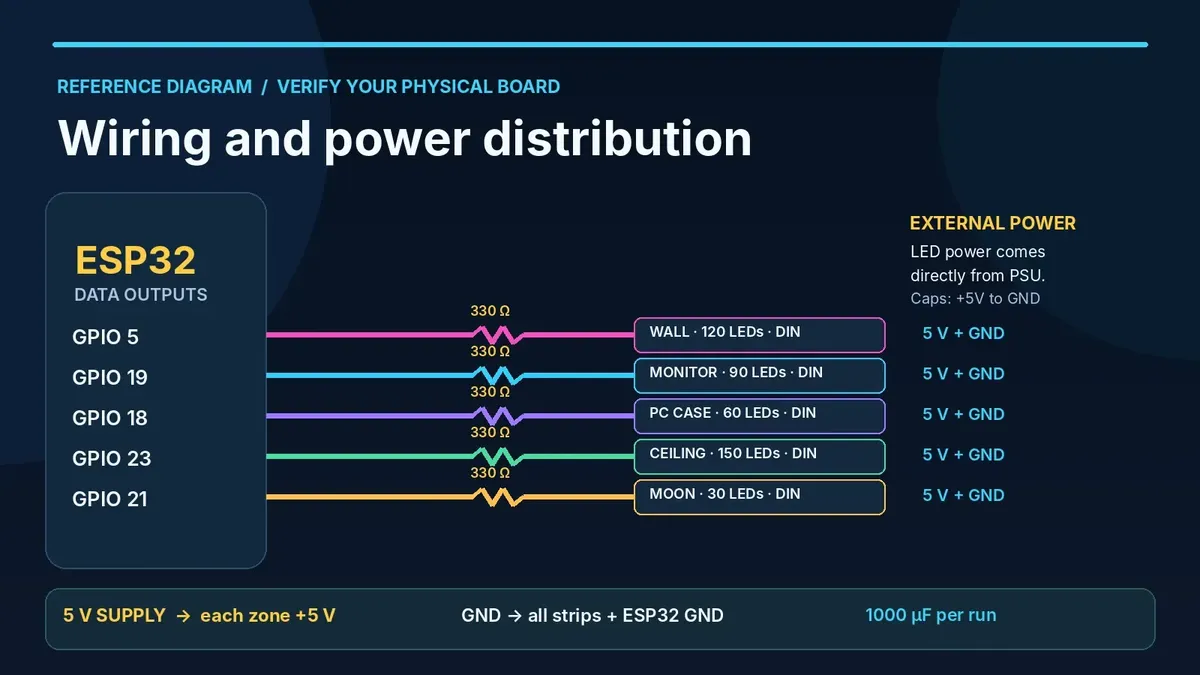
Before powering the setup, disconnect the supply and USB cable. Route each zone's GPIO data line through its own 330-ohm resistor to the strip's input marked DIN. Do not connect to the output end (DOUT). Place a 1,000 µF capacitor across +5 V and GND at the input of each LED run, with the capacitor's positive lead to +5 V and negative lead to GND.
Feed +5 V and GND to each run from suitably rated external power distribution, not through the ESP32 regulator. Join the power-supply ground and ESP32 ground. For longer strips, measure voltage at the far end while lit; add correctly fused power-injection points where required and consider feeding long runs from both ends. Follow current-carrying and wire-sizing requirements, and never join outputs of separate supplies without a designed common-return arrangement.
Power budget and signal levels
A common WS2812B worst-case planning figure is approximately 60 mA per LED at full RGB white. Using that upper-bound assumption, 450 LEDs could theoretically require about 27 A at 5 V (135 W), before engineering margin; the actual consumption depends on strip variant, color, brightness, and firmware limiting. This is a calculation for supply planning, not a measured result from the video. The published firmware configures a FastLED global power limit of 3,000 mA; do not treat a software limiter as a substitute for safe cabling, fuses and a suitably specified supply.
The ESP32 uses 3.3 V logic while WS2812B runs at 5 V. A 3.3 V data signal sometimes works at short distances, but it can be marginal: a proper 5 V-compatible, 3.3 V-driven logic buffer reduces data errors. Use a buffer compatible with WS2812B timing. GPIO5's boot-strapping role must also be checked for the exact original ESP32 board used.
Assembly and setup
Step 1
Identify the five LED runs and label them Wall (120), Monitor (90), PC Case (60), Ceiling (150) and Moon Globe (30).
Step 2
Confirm the ESP32 board's actual GPIO names; run each data line through its own series resistor to the matching DIN input.
Step 3
Connect the external supply's +5 V and GND to the LED runs using suitably sized, protected power distribution, with common ground to the ESP32.
Step 4
Install an appropriately rated 1,000 µF capacitor at each strip input and confirm polarity with a multimeter before applying power.
Step 5
Connect and test one short LED run at limited brightness before attaching all 450 LEDs.
Step 6
Install VS Code and PlatformIO, and open the original source repository as a PlatformIO project.
Step 7
Check your ESP32 board target, Wi-Fi credentials, configured zone pins and strip counts before compiling.
Step 8
Build and flash the LittleFS website and firmware using the upload method appropriate to your board; then test the local dashboard.
Step 9
Optionally add the existing Home Assistant REST configuration and dashboard card from the linked repository.
Software configuration
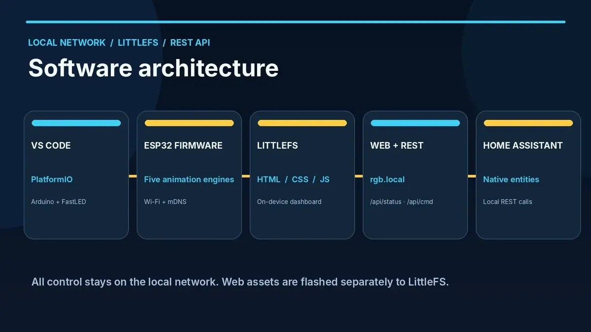
The released source is available at ESP32-Smart-LEDs on GitHub. Its project structure includes platformio.ini, src/main.cpp, data/index.html, data/assets/app.css and data/assets/app.js. The creator's original agentic-coding specification is in Prompt.txt
in the same repository.
The published firmware configures Wi-Fi credentials and its fallback access point near the top of src/main.cpp. Change the SSID, password and fallback access-point password before using the controller. The repository's current default fallback AP password is weak and must not be kept on a shared or untrusted network. Use mDNS rgb or select a different hostname.
PlatformIO board and upload caveat
The published repository's platformio.ini uses board = featheresp32, monitor_speed = 115200, LittleFS, FastLED 3.6.0 and ArduinoJson 7. It also configures a custom HTTP OTA upload referencing scripts/http_ota_upload.py. The video describes choosing an ESP32 Dev Module and using serial/USB upload. These are not equivalent defaults: verify your actual board, and configure an appropriate serial upload protocol for the first flash if the custom OTA helper is unavailable. Do not assume a fresh, unflashed ESP32 is reachable at
rgb.local.
AI coding prompt
If you prefer generating a customizable project using an AI coding assistant rather than starting with the existing source, use the creator-provided Prompt.txt. Request a PlatformIO/Arduino firmware implementation with five WS2812B outputs at GPIO 5/19/18/23/21, counts of 120/90/60/150/30, LittleFS dashboard files, local HTTP status and command endpoints, mDNS, fallback AP, and independent animation states. Review the output against the published code and test every board-dependent feature before connecting the full LED load.
Project configuration
The zone defaults from src/main.cpp are summarized in this excerpt. They are the published configuration, not newly generated or separately tested firmware:
ZoneHW ZDEF[MAX_ZONES] = { {"Wall", 5, 120}, {"Monitors", 19, 90}, {"PC Case", 18, 60}, {"Ceiling", 23, 150}, {"Moon Globe", 21, 30}, };ZoneHW ZDEF[MAX_ZONES] = { {"Wall", 5, 120}, {"Monitors", 19, 90}, {"PC Case", 18, 60}, {"Ceiling", 23, 150}, {"Moon Globe", 21, 30}, };
The firmware binds FastLED output controllers to these same five GPIO pins. If changing GPIO assignments, update both the zone definitions and their compile-time FastLED controller mappings. Changing only one section creates a mismatch.
Source code
The original source files and web assets are maintained in the public repository. The full ~1,255-line src/main.cpp is not duplicated in this editorial package: using the repository avoids publishing an incomplete or out-of-sync copy. See the repo's Home-Assistant-Config, Home-assistant-dashbaord-card.txt and Prompt.txt for the creator's integration and development files.
Build and upload
With a matching board configuration and a usable serial-upload setup, compile the ESP32 firmware using PlatformIO:
pio runpio run
The video uses these additional commands for a USB/serial upload workflow:
pio run -t uploadfs pio run -t uploadpio run -t uploadfs pio run -t upload
Important: The published platformio.ini may override upload to use its custom HTTP OTA command. Check the file and select your actual first-flash method before running an upload; do not use the OTA upload target for a new device that has not yet been provisioned. Upload LittleFS assets as well as the program, or the browser page can be absent even when the firmware starts.
After startup, use http://rgb.local when mDNS resolves; otherwise find the device's LAN IP in the serial monitor or router. If Wi-Fi connection fails, check the fallback AP name configured in firmware and join it to reach the device's local interface.
Test the result
Step 1
Power a single zone at low brightness and confirm it responds without flicker or overheating.
Step 2
Open http://rgb.local and confirm that the dashboard appears; use the local IP if mDNS is unavailable.
Step 3
Set Wall, Monitor, PC Case, Ceiling and Moon Globe to different brightness, color or effect values and verify independent control.
Step 4
Use a synchronized/global preset and confirm that it updates the intended zones.
Step 5
Request the status endpoint from a device on the same trusted LAN and check the JSON response.
Step 6
Add the original Home Assistant REST integration and verify that Home Assistant sees and controls the expected lights.
Step 7
Check power voltage at the far end of the longest lit strip and inspect wiring temperature under a representative load.
For a basic network check:
curl http://rgb.local/api/statuscurl http://rgb.local/api/status
For a global OFF command on a trusted local network, the repository's API accepts a JSON POST similar to:
curl -X POST http://rgb.local/api/cmd -H "Content-Type: application/json" -d '{"all":true,"cmd":"OFF"}'curl -X POST http://rgb.local/api/cmd -H "Content-Type: application/json" -d '{"all":true,"cmd":"OFF"}'
These commands are documentation examples based on the published API; they have not been executed against this specific room controller while preparing the article.
Home Assistant integration
Home Assistant polls
http://rgb.local/api/status
and sends JSON commands to
http://rgb.local/api/cmd
. The original source repository includes an example REST sensor, REST commands, light template, and custom dashboard card. Use the source versions rather than mixing field names from unrelated ESP32 projects.
Copy the provided Home Assistant configuration to the appropriate configuration.yaml
or packages location for your installation, after inspecting for existing rest: rest_command: and template: keys. Validate configuration, reload or restart the appropriate Home Assistant integrations, and add the creator's dashboard card through the manual card editor.
Ensure Home Assistant can resolve rgb.local on its own network, or replace that hostname with a stable IP or network name. This project integrates over local REST; it does not require cloud APIs.
Troubleshooting
LEDs flicker or change color unexpectedly
Confirm the ESP32 and LED strips share a ground, the data line reaches DIN, the data-resistor connection is secure, and the 5 V supply does not sag under load. Add a correctly selected 3.3 V-to-5 V buffer where appropriate.
White LEDs turn pink or dim near the end
Measure 5 V at the far end with the strip illuminated. Lower brightness or improve current-rated wiring and add protected power-injection points. A capacitor does not solve steady-state voltage drop from undersized wiring.
The dashboard does not load
Check that the LittleFS data partition was actually flashed, verify Wi-Fi status, and open the ESP32's current IP address if rgb.local is not resolvable. The fallback access point only becomes available according to the firmware's connection logic.
Upload fails or tries an HTTP endpoint
The source repository specifies a custom OTA upload protocol. For a new controller, use a verified serial first-flash configuration matching the physical board and check the PlatformIO board ID before changing any upload commands.
Home Assistant entities show unavailable
Test
/api/status
from the Home Assistant host, confirm mDNS resolution or use a fixed IP, check its YAML structure and reload the relevant configuration. The API command endpoint is
/api/cmd
, not
/api/command.
Safety and limitations
Never power hundreds of LEDs from an ESP32 GPIO, USB port or its small regulator. A 5 V supply with substantial output current requires appropriately rated connectors, conductors, strain relief, insulated terminals and branch fusing. If the power supply connects to mains voltage, use an enclosed certified unit and keep all exposed wiring on the safe low-voltage side.
The published controller enables the HTTP command path without an authentication check in handleCmd(), and its default HTTP_USER and HTTP_PASS values are blank. Treat the API as unauthenticated local control in the supplied source, isolate it on a trusted LAN, and avoid public port forwarding. Review firmware security before exposing the device to guest networks or the internet.
The exact board revision, supply model, fuse arrangement, wiring gauge, actual maximum current draw and individual strip lengths were not supplied. They must be verified for your own installation. The images in this article include illustrative renders; use the written pin table and your physical board labeling as the connection authority.