On This Page
Introduction
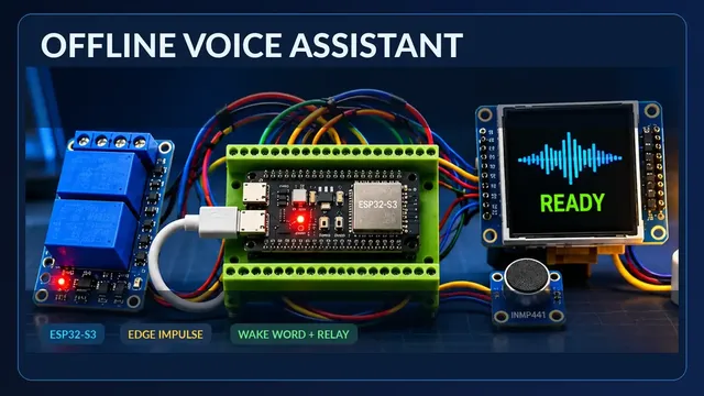
This project builds an offline, keyword-based voice controller with an ESP32-S3, an INMP441 digital microphone, a 1.77-inch SPI TFT display, and a relay module. A small audio-classification model trained in Edge Impulse recognizes the wake word “Marvin” and two commands: “turn on” and “turn off.” The ESP32-S3 runs the exported model locally and switches the relay while showing its status on the TFT.
The firmware demonstrated in the video does not need Wi-Fi, an internet connection, or a cloud speech service during operation. Dataset preparation and model training, however, use a computer and the online Edge Impulse service. This is a fixed-vocabulary TinyML controller, not a general-purpose conversational AI or unrestricted speech-to-text assistant.
The video demonstrates the two voice commands controlling the relay. The complete original source, model-training materials, and agentic-coding prompts are linked in the project repository.
What you will build
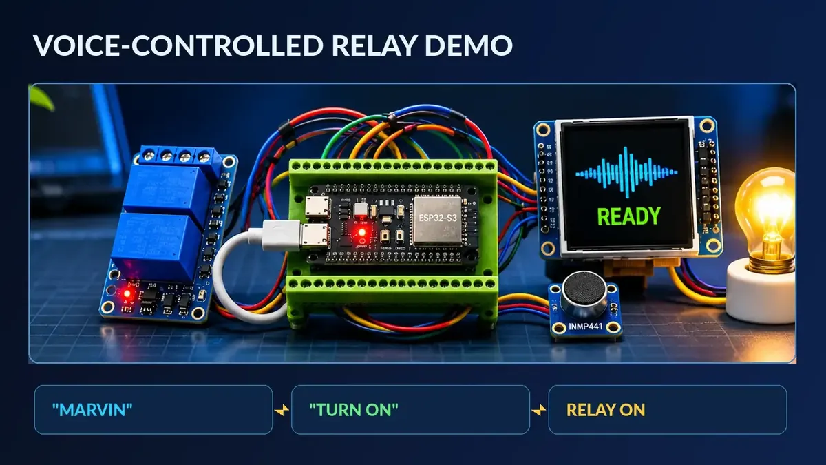
The finished device listens for a custom wake word, opens a short command-listening window, classifies a spoken command, and changes a relay output. The TFT shows the current listening or action state and microphone activity.
The demonstrated interaction is:
Step 1
Say “Marvin” to activate command listening.
Step 2
Say “turn on” to switch the relay on.
Step 3
Say “Marvin” again to start another command window.
Step 4
Say “turn off” to switch the relay off.
The voice classification runs locally on the ESP32-S3; the relay's attached load should first be tested using a safe, low-voltage circuit.
What you will need
Components
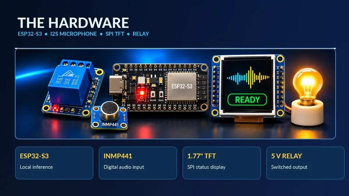
| Qty | Component | Notes |
|---|---|---|
| 1 | ESP32-S3 development board | Video uses an ESP32-S3; verify your board's flash, PSRAM, and exposed GPIO pins. |
| 1 | INMP441 I2S microphone module | Digital audio input; powered from 3.3 V. |
| 1 | 1.77-inch SPI TFT display | ST7735-compatible display used in the reference agent prompt; check the actual module controller. |
| 1 | 5 V relay module | One channel is controlled via GPIO7; verify its input accepts 3.3 V logic. |
| 1 | Regulated 5 V power supply | Adequate current and correct polarity are required. |
| As needed | Jumper wires and USB cable | Common ground between all connected low-voltage modules. |
| Optional | Low-voltage test lamp or LED load | Recommended instead of experimenting with mains wiring. |
Software
Visual Studio Code with the PlatformIO IDE extension.
Python 3 with pyserial, to collect labeled audio samples from the board.
Edge Impulse for audio feature generation, classification training, testing, and Arduino-library export.
Codex or another coding agent, if reproducing the agentic-coding workflow.
Original project repository for creator-supplied firmware, recording code, model-training material, and prompts.
Prerequisites
Be able to identify the GPIO pins on your ESP32-S3 board, install a PlatformIO toolchain, choose a serial COM port, and check power-supply polarity. You also need access to Edge Impulse to train the model. Training occurs before deploying the offline firmware.
How it works
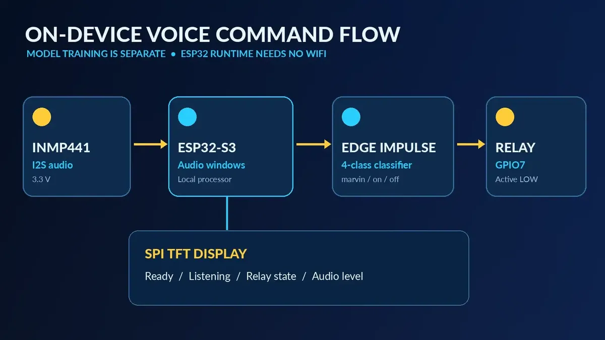
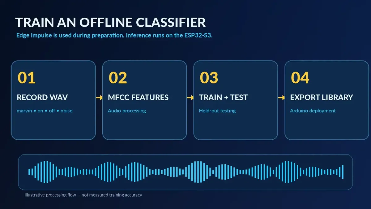
The INMP441 sends digital microphone samples to the ESP32-S3 over I2S. The firmware prepares audio windows in the format expected by the trained model and performs Edge Impulse audio classification on-device. In the video's training workflow, an MFCC audio processing block converts sound into features, and a classification block learns four classes: noise, marvin, turn_on, and turn_off.
Once deployed, the firmware first watches for marvin. The original firmware-generation prompt specifies a 10-second window after wake-word recognition. During this window it accepts a turn_on or turn_off classification and drives GPIO7. The prompt explicitly defines the relay input as active-low: a LOW output activates the relay, and HIGH deactivates it. This polarity must be checked against your actual module.
The TFT is a separate SPI peripheral that displays ready, listening, and relay-action status. Its screen is a status interface, not the source of the voice-recognition logic.
Two different phases
Training phase — computer and internet: record labeled .wav
samples, upload them to Edge Impulse, generate MFCC features, train and test a classifier, then export an Arduino library.
Runtime phase — ESP32-S3, offline: capture live microphone audio, run the exported model locally, interpret its limited class labels, and switch the relay.
Understanding the pins
The following connections are explicitly stated in the video. All GPIO numbers refer to the ESP32-S3 development board, not to physical header positions; header layouts differ between board manufacturers.
Wiring and connections
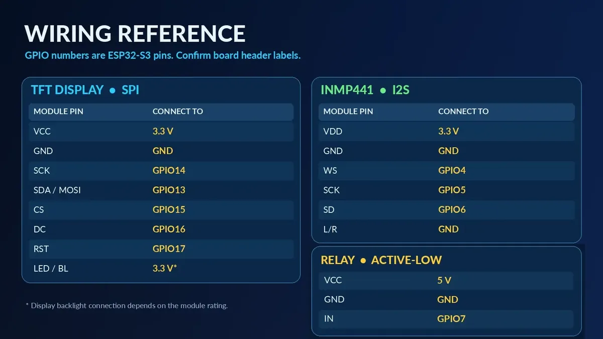
TFT display — SPI
| Pin | Signal | Notes |
|---|---|---|
| TFT VCC | ESP32-S3 3.3 V | Use only a module rated for 3.3 V supply and logic. |
| TFT GND | ESP32-S3 GND | Common ground. |
| TFT SCK | ESP32-S3 GPIO14 | SPI clock. |
| TFT SDA / MOSI | ESP32-S3 GPIO13 | SPI data from microcontroller to display. |
| TFT CS | ESP32-S3 GPIO15 | Display chip select. |
| TFT DC | ESP32-S3 GPIO16 | Data/command select. |
| TFT RST | ESP32-S3 GPIO17 | Display reset. |
| TFT LED / BL | ESP32-S3 3.3 V | Backlight, only if the module's circuit supports direct 3.3 V connection. |
INMP441 microphone — I2S
| Pin | Signal | Notes |
|---|---|---|
| INMP441 VDD | ESP32-S3 3.3 V | Do not power the microphone from 5 V. |
| INMP441 GND | ESP32-S3 GND | Common ground. |
| INMP441 WS | ESP32-S3 GPIO4 | I2S word-select clock. |
| INMP441 SCK | ESP32-S3 GPIO5 | I2S bit clock. |
| INMP441 SD | ESP32-S3 GPIO6 | I2S data input to ESP32-S3. |
| INMP441 L/R | GND | Selects left-channel audio in the demonstrated configuration. |
Relay module and power
| Pin | Signal | Notes |
|---|---|---|
| Relay VCC | Regulated 5 V | Supply voltage stated in the video; verify module rating. |
| Relay GND | ESP32-S3 GND | Must share ground with the controller's low-voltage circuit. |
| Relay IN | ESP32-S3 GPIO7 | The original final-firmware prompt expects an active-low relay. |
| ESP32-S3 5V / VIN | Regulated 5 V | Only use a board pin specifically rated for regulated 5 V input. |
| ESP32-S3 GND | Supply negative / GND | Shared low-voltage reference. |
Connect the load to the relay's contact terminals only after verifying the module's terminal labels, contact ratings and safe wiring practice. The relay's contact side is electrically separate from the GPIO control signal. Do not connect mains power to the ESP32-S3 or any logic signal pin.
Assembly and setup
Step 1
With every supply disconnected, connect the TFT and INMP441 using the pin tables above.
Step 2
Connect the relay's input to GPIO7 and its low-voltage supply to the regulated 5 V source. Join low-voltage grounds.
Step 3
Check each module's voltage rating and verify continuity, polarity and absence of shorts before powering the circuit.
Step 4
Open the project repository and use its recorder project and prompt_recorder.txt as the source for the dataset-recording stage.
Step 5
Connect the ESP32-S3 by USB, identify its serial port in PlatformIO, and upload the recorder firmware.
Step 6
Install Python and pyserial, adjust the COM port in the original record.py, and start recording the four labels.
Step 7
Train and test your own Edge Impulse classification model, then export the matching Arduino library.
Step 8
Prepare the final PlatformIO firmware from the original repository or its prompt_final.txt, integrate the exported library, build and flash.
Step 9
Start with a low-voltage test load and verify the ready, wake, command and relay states.
Record a custom voice dataset
The recording-stage firmware streams microphone data to a Python script running on your computer. The original recorder-generation prompt specifies 16 kHz, 16-bit mono WAV, with about 2 seconds for the wake word and 2.5 seconds for the other classes. The recording script saves each selected class into its own directory.
The labels in the demonstration are:
marvin — the custom wake word.
turn_on — spoken “turn on.”
turn_off — spoken “turn off.”
noise — background sounds without a command.
Collect at least 50–100 samples per label as suggested in the video. Vary speaking distance and room conditions, and capture background sounds from the intended installation location. Review the recorder's quality warnings: discard clipped, quiet, truncated or mislabeled samples.
After flashing the matching recorder firmware, the commands shown in the demonstration are:
python -m pip install pyserial python record.pypython -m pip install pyserial python record.py
record.py is supplied through the original repository, not recreated in this article. Select the serial port required by that script before running it. The script and recorder firmware must use compatible baud rates and framing; the repository's recorder prompt specifies 921600 baud.
Train the model in Edge Impulse
Step 1
Sign in at Edge Impulse and create an audio classification project.
Step 2
Upload the .wav files for marvin, turn_on, turn_off, and noise, setting the matching labels.
Step 3
Set aside representative test data that is not reused for training.
Step 4
Create an impulse using a 1,000 ms audio window as shown in the video; check that this window fits the spoken classes and sampled data.
Step 5
Add MFCC audio processing and a classification learning block; the video also mentions MFE as an alternative to consider.
Step 6
Generate features, inspect the feature explorer, and train the classifier.
Step 7
Evaluate the confusion matrix and the held-out model testing results, rather than treating training accuracy as the final measure.
Step 8
Select Deployment → Arduino library, build, and download your exported inference library.
In the demonstration, the Edge Impulse interface uses an Espressif ESP-EYE / ESP32 240 MHz target profile and settings described as 8 MB RAM, 16 MB ROM, and 300 ms latency. These are the selected modeling/profile settings in the video, not verified specifications of every ESP32-S3 board. Verify the actual board memory and the model's runtime requirements before deployment.
If the classifier frequently confuses turn_on with turn_off, improve labeling and sampling conditions, add more representative examples, or modify the command vocabulary. No quantitative accuracy percentage is provided here because the source material does not establish a tested value.
AI coding prompt
The creator's original prompts are provided in the repository as prompt_recorder.txt and prompt_final.txt. For the closest reproduction, use those files. The following is a newly written project brief, not the original verbatim prompt and not a claim of newly tested firmware:
Build an ESP32-S3 PlatformIO/Arduino offline voice-command relay project. Use an INMP441 on I2S WS=GPIO4, SCK=GPIO5, SD=GPIO6, with L/R connected to GND for left-channel audio. Use an ST7735-compatible SPI TFT: MOSI=GPIO13, SCK=GPIO14, CS=GPIO15, DC=GPIO16, RST=GPIO17. Drive an active-low relay input from GPIO7 (LOW=ON, HIGH=OFF), initializing the relay safely in the OFF state. Integrate the Edge Impulse Arduino library exported by the user. Use its actual model settings, sampling frequency, and class names: noise, marvin, turn_on, turn_off. Keep the device offline during normal operation. Require a confident 'marvin' detection before allowing a command. Open a 10-second command window, then accept turn_on or turn_off. Display Ready, Listening, Switching ON/OFF and error states on the TFT and report classifications to the serial monitor. Write maintainable functions for I2S acquisition, classifier buffering, relay output, UI states and serial diagnostics. Handle mic or inference failures by leaving the relay in a safe, documented state. Check compatibility with my actual Arduino-ESP32 and Edge Impulse versions rather than inventing APIs. Generate PlatformIO files. Do not claim that the firmware compiles or works without tests.Build an ESP32-S3 PlatformIO/Arduino offline voice-command relay project. Use an INMP441 on I2S WS=GPIO4, SCK=GPIO5, SD=GPIO6, with L/R connected to GND for left-channel audio. Use an ST7735-compatible SPI TFT: MOSI=GPIO13, SCK=GPIO14, CS=GPIO15, DC=GPIO16, RST=GPIO17. Drive an active-low relay input from GPIO7 (LOW=ON, HIGH=OFF), initializing the relay safely in the OFF state. Integrate the Edge Impulse Arduino library exported by the user. Use its actual model settings, sampling frequency, and class names: noise, marvin, turn_on, turn_off. Keep the device offline during normal operation. Require a confident 'marvin' detection before allowing a command. Open a 10-second command window, then accept turn_on or turn_off. Display Ready, Listening, Switching ON/OFF and error states on the TFT and report classifications to the serial monitor. Write maintainable functions for I2S acquisition, classifier buffering, relay output, UI states and serial diagnostics. Handle mic or inference failures by leaving the relay in a safe, documented state. Check compatibility with my actual Arduino-ESP32 and Edge Impulse versions rather than inventing APIs. Generate PlatformIO files. Do not claim that the firmware compiles or works without tests.
The source repo's final prompt contains more detailed decision thresholds, mic-level filters and timing values. Those settings should be carried over when attempting an exact reproduction, and then tested with the actual microphone and model.
Integrate the trained model
After downloading the Edge Impulse Arduino deployment ZIP, extract it and place the required exported source files inside a named local library directory under the PlatformIO project's lib/. The video describes creating a library.json file so PlatformIO discovers the local library. Use the actual exported library name and include header, which vary by Edge Impulse project.
The original generated firmware references a project-specific inference header. Do not assume that an unrelated exported Arduino library has the same header or that a regenerated model preserves the same class order. Check the generated model-parameters and required classifier API before compiling.
Build and upload
With the correct board environment, library dependencies and serial port configured in your PlatformIO project:
pio run pio run -t uploadpio run pio run -t upload
To read debug output, use the monitor speed set by your final firmware configuration (the original final-coding prompt specifies 115200 baud):
pio device monitor -b 115200pio device monitor -b 115200
These are the build and upload commands demonstrated in the video. This ZIP is a Wagtail article package, not a validated firmware release: download the actual firmware and Edge Impulse export from the creator's repository/materials when building the device.
Test the result
Step 1
Boot the ESP32-S3 and check that the TFT indicates the ready state without using Wi-Fi.
Step 2
Say “Marvin” and verify the display enters the listening state.
Step 3
Say “turn on” and check whether the relay switches the low-voltage test load on.
Step 4
Wait for the system to return to its ready state.
Step 5
Say “Marvin”, then “turn off”, and confirm the output switches off.
Step 6
Test with background noise and ordinary conversation to check for accidental triggering.
Step 7
Disconnect the network and repeat to confirm that on-device inference operates without an internet service.
The video shows the on/off interaction; the tests above are a repeatable checklist, not a claim that every noise or failure scenario was measured in the video.
Troubleshooting
Microphone is silent or predictions never change
Check INMP441 VDD=3.3 V, GND, WS on GPIO4, SCK on GPIO5, SD on GPIO6, and L/R at GND. Confirm that firmware reads the left I2S slot at the sampling rate required by the exported model.
TFT remains blank or displays incorrectly
Check the 3.3 V supply, backlight requirements, SPI MOSI/SCK and CS/DC/RST wiring. Confirm the TFT controller and initialization profile actually match the installed 1.77-inch display.
Wake word is detected but commands fail
Verify that the class names in firmware match the exported model (marvin, turn_on, turn_off, noise), that commands are spoken during the listening window, and that the recorded training set covers the intended voice and noise environment.
Relay operates in reverse or fails to switch
The original final prompt assumes an active-low module. Check its input polarity, 5 V supply, 3.3 V GPIO-level compatibility, and contact wiring. Do not solve this by changing unknown high-voltage wiring while powered.
Model does not fit or build fails
Confirm ESP32-S3 flash/PSRAM capacity, the PlatformIO board ID, exported inference library structure, C++ header name, and compatibility of the Arduino-ESP32/I2S APIs. The Edge Impulse target profile is not a substitute for checking your physical board.
Safety and limitations
Runtime offline does not mean training offline. Edge Impulse account access, dataset upload, and training require an online workflow in this demonstration.
This is a four-label keyword classifier, not a general speech recognizer, chatbot, text-to-speech engine, or arbitrary natural-language assistant.
Power the INMP441 from 3.3 V. Use the display voltage and backlight requirements of the actual module; do not assume all ST7735 breakouts have identical regulators or resistor networks.
The relay can have 5 V coil power while its input must still be compatible with the ESP32-S3's 3.3 V GPIO. Never apply 5 V to an ESP32-S3 GPIO.
Mains voltage can cause serious injury or fire. For a first build, use a low-voltage test circuit. Mains-side wiring must follow local electrical requirements and be performed by a qualified person.
A GPIO relay may switch unexpectedly during resets or firmware updates unless the actual board/module design provides a safe default. Validate the boot state with the load disconnected.
Review AI-generated code, generated dependencies, power wiring, and model class order; using a coding agent does not replace electrical or software verification.